| PCB5-1-B-13V 包括如下所示部分。
PCB5-1-B-13V的装配材料清单
| NO. |
描述 |
Quantity |
Specification |
Remark |
| 1 |
Photo coupler |
1 |
TLP521 |
U1 |
| 2 |
LED |
1 |
RED |
D1 |
| 3 |
LED HOLDER |
1 |
D3.0*2 Holes*9mm |
D3.0*2 Holes*9mm |
| 4 |
Resistor |
2 |
330E |
R1,R2 |
| 5 |
2pin socket |
5 |
CON2 |
J1,J2,J3,J4,J5 |
| 6 |
Resistor |
1 |
10K |
R3 |
PCB5-1-B-13V的电路图

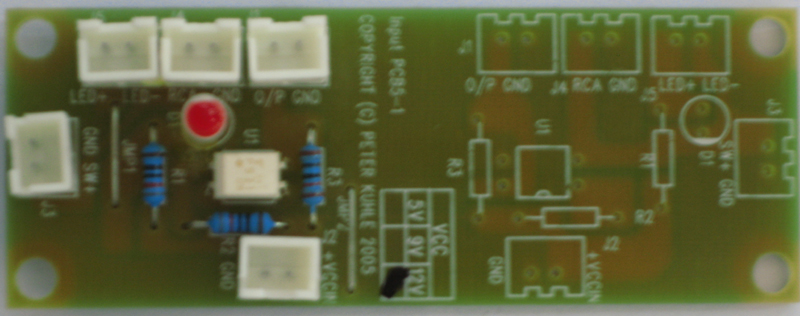
PCB5-1-B-13V的电路板图

|
PCB5-1-B-13V装配说明 1.检查是否有刮伤,标记,痕迹保证产品完整如新.
2.电路板没有弯曲情况.
3.确保所有的零件如装配材料清单所示准确无误.
4.安装零件和组件时在一定程度上确保它们看起来整齐有序.
5.确保所有已经焊接的部位完整地被覆盖并看起来有光泽.
6.小心确保没有漏焊接的部分,正如我们不希望在焊盘之间会产生短路.
7.如果有旧的线路确保线路被绝缘完整覆盖.
|
|
检查步骤:
1.检查所有的元器件与BOM上要求的一样
2.检查所有的元器件必须安装整齐并看起来良好
3.检查所有的焊点良好并表面光滑
4.检查所有的焊点没多锡,少锡,短路等
5.检查所有的焊点部位没有多余翘起,没有和其它线路衔接造成短路
6.检查细小铜箔走线没断短线等
7.检查如果有增加的绝缘飞线应焊接良好没短路现象 |
|
PCB5-1-B-13V调试说明 |
|
 |
| Connect as per the above diagram |
| Note there is two
separate circuit of the above schematic on this PCB |
| 1. Connect DC13V to
either J2 ensure positive to pin 1. |
| 2. Plug a 2-pin plug of
momentary spring return switch to both J3 and another to J4. |
| 3. Connect a voltage
meter to J1. |
| 4. With DC13V applied
and all switches are in open position, the LED must be off and
voltage meter read 13Vdc. |
| 5. With DC 13V applied
and one or more of the momentary switch in the closed position, the
voltage meter must read 0V and the LED be on and bright. |
| 6. Repeat test for
other section of PCB |
| 7. If the above is correct the circuit board has passed tested.
Apply serial number stamp. |
|
Top<<Back to last Page >>Main
Menu
COPYRIGHT © PETER KUHLE 2006
|