| PCB5-1-B-5V 包括如下所示部分。
PCB5-1-B-5V的装配材料清单
|
描述 |
数量 |
参考 |
零件 |
|
Photo coupler |
3 |
U1 |
TLP521 |
|
Photo coupler |
1 |
U1 |
TLP521 |
|
Photo coupler |
2 |
U1 |
TLP521 |
|
Photo coupler |
1 |
U1 |
TLP521 |
|
LED |
3 |
D1 |
RED |
|
LED HOLDER |
3 |
D3.0*2 Holes*9mm |
D3.0*2 Holes*9mm |
|
Resistor |
6 |
R1,R2 |
330E |
|
LED |
1 |
D1 |
RED |
|
LED HOLDER |
1 |
D3.0*2 Holes*9mm |
D3.0*2 Holes*9mm |
|
Resistor |
2 |
R1,R2 |
330E |
|
LED |
1 |
D1 |
RED |
|
LED HOLDER |
1 |
D3.0*2 Holes*9mm |
D3.0*2 Holes*9mm |
|
Resistor |
2 |
R1,R2 |
330E |
|
LED |
1 |
D1 |
RED |
|
LED HOLDER |
1 |
D3.0*2 Holes*9mm |
D3.0*2 Holes*9mm |
|
Resistor |
2 |
R1,R2 |
330E |
|
2pin socket |
15 |
J1,J2,J3,J4,J5 |
CON2 |
|
2pin socket |
5 |
J1,J2,J3,J4,J5 |
CON2 |
|
2pin socket |
5 |
J1,J2,J3,J4,J5 |
CON2 |
|
2pin socket |
5 |
J1,J2,J3,J4,J5 |
CON2 |
|
Resistor |
3 |
R3 |
10K |
|
Resistor |
1 |
R3 |
10K |
|
Resistor |
1 |
R3 |
10K |
|
Resistor |
1 |
R3 |
10K |
PCB5-1-B-5V的电路图

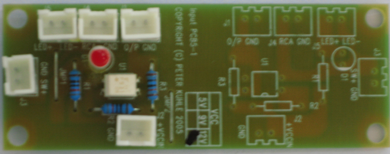
PCB5-1-B-5V的电路板图

| Inspection Instruction of
PCB5-1-B-5V |
| 1.Check for scratches, marks, and appearance of tracks are
clean with a good finish. |
| 2.board should not be warped. |
| 3. Ensure all parts are exactly as per BOM (Bill of material) |
| 4. Ensure all components have been installed
to look good with a straight looking alignment |
| 5. Ensure the finish of soldering covers the
whole pad and has a shine. |
| 6. Check to ensure no excess solder is left,
as we don't want the possibility of creating shorts between pads |
| 7. Check insulation of wires is full
covering with no exposed wire. |
| |
|
Testing Instruction of PCB5-1-B-5V |
|
 |
参考测试线路图
注意此PCB有两块相同分开的线路组成,PCB6-1-B-5V表示用底部的部分,PCB6-1-T-5V表示用顶部的部分,PCB6-1-2-5V表示用顶部和底部两部分都用
连接一个5VDC电源到J2,注意极性不能接反,J2的第一脚为正极
连接一个自复位开关到J3和J4
连接一个电压表到J1
接上电源到,未闭合连接到J3;J4开关时,连接到J1的电压表读数应是5VDC,相应的LED灯应不亮
闭合连接到J3;J4的任一开关时,连接到J1的电压表读数应是零,相应的LED灯应亮
如是PCB6-5-2-5V板,重复上述测试在另一部分
如上述测试合格,打上序列号码 |
顶部<返回上一页>主菜单
COPYRIGHT © PETER KUHLE 2006
|